


 Home » Applications »


Cutting Tools for Aerospace Components and Difficult-to-Machine Materials
Help customers evaluate tooling for titanium, nickel alloys, aluminum structures and high-strength steel by reviewing the component, operation, setup and recorded result.
 Discuss an Aerospace Application
Start With the Component and Operation
Aerospace machining requirements vary depending on component design, material characteristics and machining operation. Reviewing the actual component first helps identify the tooling options that match the application.
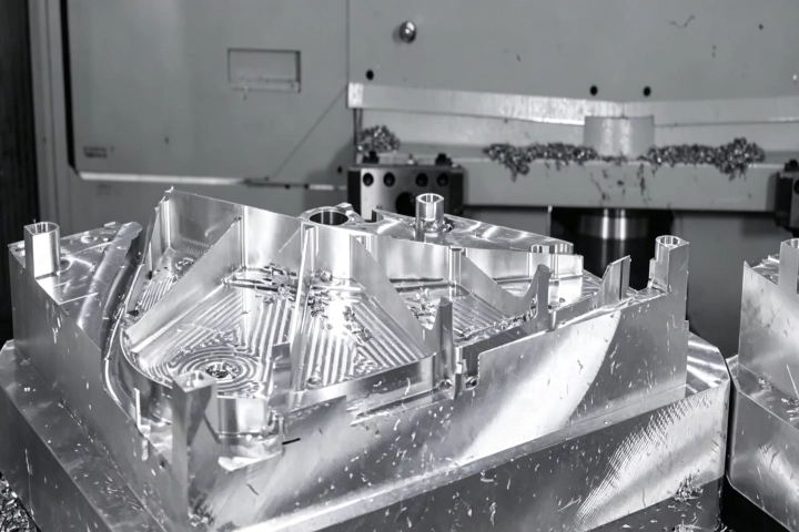
Structural Frames & Beams
Ribs, bulikheads, spars and structural assemblies
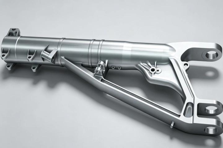
Landing Gear & Shafts
Struts, trunnions, pins and torque links
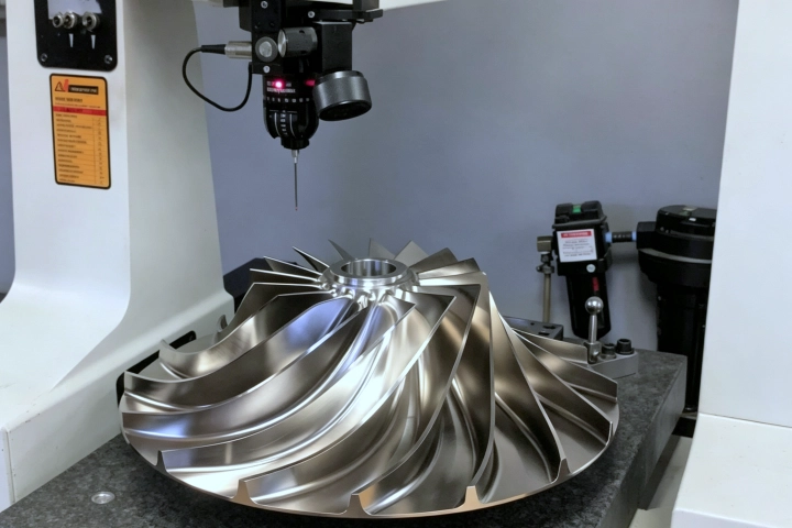
Engine & Actuation Components
Blisks, casings, housings and control parts
What to Check First in Aerospace Machining
01
Heat at the Cutting Edge
Check First: Confirm material, speed range, tool engagement and coolant delivery.
Why It Matters: Titanium and nickel alloys can generate significant heat during machining, making thermal control an important factor.
02
Short Batches & Changeovers
Check First: Review tool sharpness, dwell, toolpath and feed stability.
Why It Matters: Poor cutting stability can increase work hardening and make subsequent machining more difficult.
03
Thin Walls & Distortion
Check First: Check clamping, tool pressure, stock sequence and part support.
Why It Matters: Thin aerospace structures require careful control of machining forces to maintain part stability.
04
Wear Consistency
Check First: Record edge wear and results across multiple parts instead of relying on one best cut.
Why It Matters:
Repeatable machining performance provides more reliable evaluation than a single peak result.
Materials and Tooling Considerations
Different engineering materials create different wear, chip-control and setup requirements. Start with the material and operation before narrowing down the tooling option.
| Material | Typical Parts | Common Operations | What to Confirm |
|---|---|---|---|
| Titanium Alloys | Frames, beams, fittings, structural parts | Milling, turning, drilling | Alloy, engagement, heat control, rigidity |
| Nickel-Based Alloys | Engine and hot-section components | Turning, profiling, grooving | Material condition, heat, notch wear, coolant |
| Aluminum Alloys | Structural frames, housings, plates | High-feed milling, drilling, boring | Alloy, chip evacuation, built-up edge, thin walls |
| High-Strength Steel | Landing gear, shafts, fasteners | Turning, milling, drilling | Strength, hardness, scale, interrupted surfaces |
Application Note: Avoid presenting universal speed-and-feed recommendations. Actual results depend on tooling geometry, machine condition, holder stability, coolant delivery and workpiece setup.
Relevant Tool Families
Explore the cutting tool categories commonly considered for aerospace machining applications.
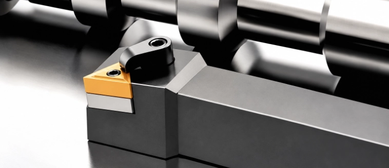
Turning & Profiling Inserts
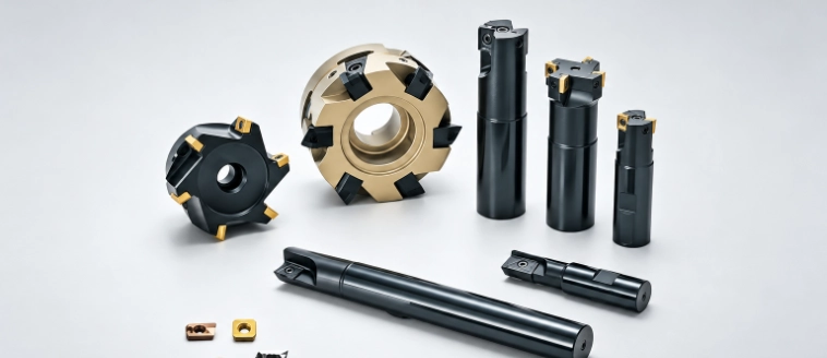
Milling Inserts & Cutters
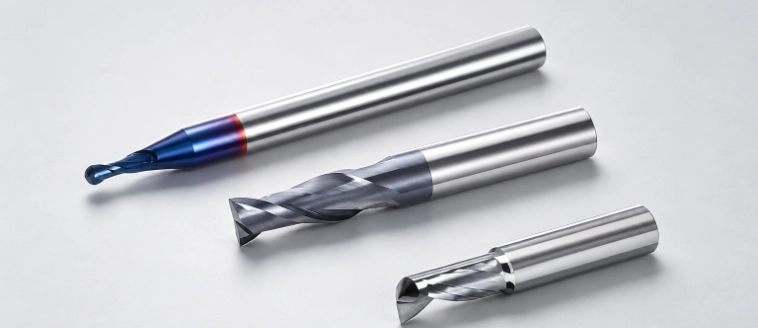
Solid Carbide End
Mills
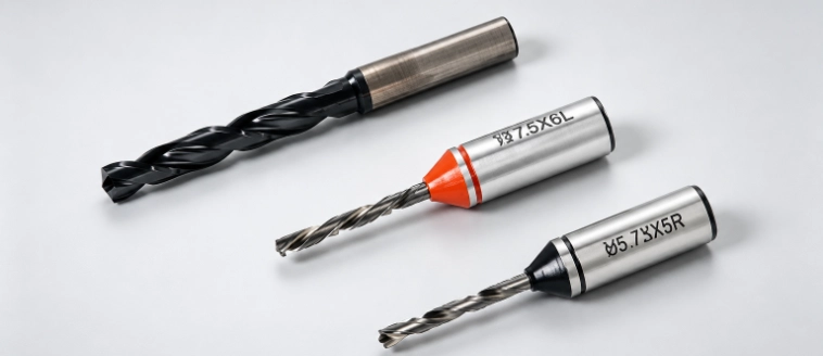
Solid Carbide
Drills
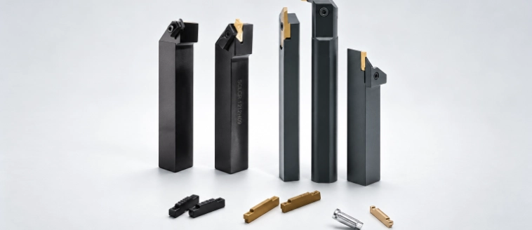
Grooving & Parting Tools
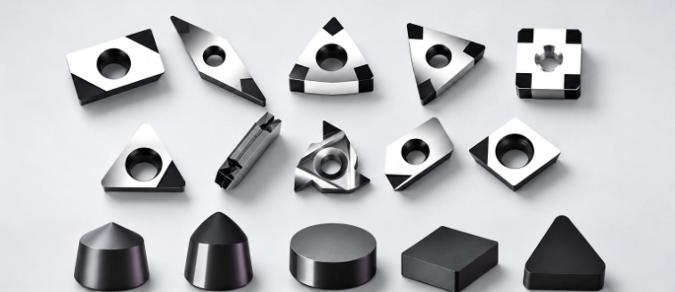
PCD, PCBN & Specialty Tools
Your Attractive Heading
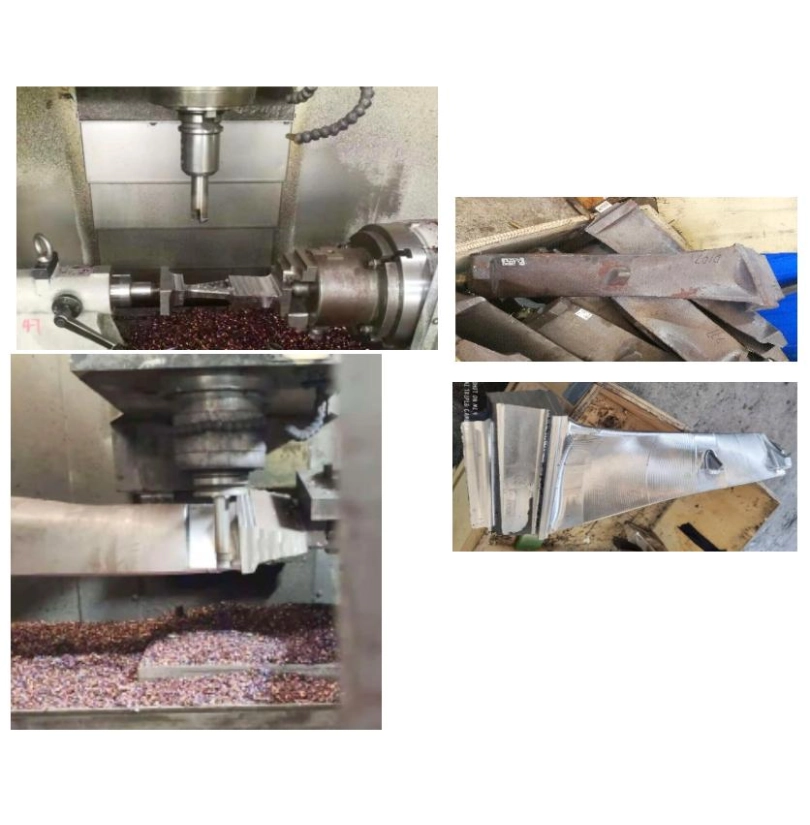
Full-Program Milling Test on a Fifth-Stage Rotor Blade
🔸Part: Fifth-Stage Rotor Blade
🔸Material: Q345C · HB200
🔸Operation: Milling · No Coolant
| Competitor Baseline | Premitools Test 1 | Premitools Test 2 | |
|---|---|---|---|
| Milling Insert | RPHT1204MO-JC400 | RY-R6-502 | RY-R6-502 |
| Grade | Competitor | B502A+P13 | B502D+P13 |
| Cutting Speed | 188.4 m/min | 188.4 m/min | 188.4 m/min |
| Feed per Tooth | 0.625 mm/z | 0.625 mm/z | 0.625 mm/z |
| Depth of Cut | 1 – 3 mm | 1 – 3 mm | 1 – 3 mm |
| Recorded Result | Completed one full program | Completed one full program | Completed one full program |
Same Parameters · Full Program Completed · No Initial Edge Chipping
Both Premitools grades completed the full machining program under the same recorded conditions. No edge chipping was found during the initial trial, and B502A+P13 showed slightly less wear. The customer planned a 1,000-piece follow-up trial.
Full test report and wear photos are available on request
How We Help You Evaluate Another Option
A cross-reference is only the starting point. The application decides what is worth testing.

Step 01 Review the Component and Material
-
Start with the actual application by reviewing the material specification, machining operation, setup, current tool and performance target. This information helps define the conditions before evaluating alternative tooling options.

Step 02 Narrow the Trial Options
-
Based on the application requirements, select only the geometries and grades relevant to the material behaviour, heat generation, tool reach and machining stability. This keeps testing focused on practical solutions.
Step 03 Record the Trial Result
-
Evaluate the trial based on wear behaviour, cycle outcome, surface finish and part-to-part consistency. Recorded results provide a clearer understanding of whether the tooling option performs consistently.
FAQs
-
What information should I provide for an aerospace machining review?

-
Share the material specification, component feature, operation, current tool, holder, machine, coolant and recorded machining problem.
-
Do you claim aerospace certification?
-
No. This page focuses on cutting-tool application support and does not represent aerospace-part approval, certification or customer qualification.
-
Can you review tools for titanium and nickel alloys?
-
Yes. The application should first be reviewed based on material condition, operation, engagement and setup.
-
How should a trial result be compared?
-
Compare wear pattern, usable tool life, finish, dimensional stability and part-to-part variation under the same recorded conditions.
-
Can we start with a small trial quantity?
-
Yes, subject to availability. Small trials help reduce qualification risk before moving toward repeat supply.
Have a Current Application to Evaluate?
Send the current tool code and brief application details. We will review the material, operation and what needs to improve before suggesting a practical next step.


