


 Home » Applications »


Cutting Tools for Pipeline, Valve and Wind-Energy Components
Help customers evaluate tooling for pipeline connections, valves, large flanges and wind-energy components by reviewing the material, scale, interrupted surfaces, setup and target result.
 Discuss an Energy Application
Start With the Component and Operation
Energy component machining involves large dimensions, demanding materials and complex cutting conditions. Reviewing the component type, material condition and machining operation helps identify tooling options that match the application.
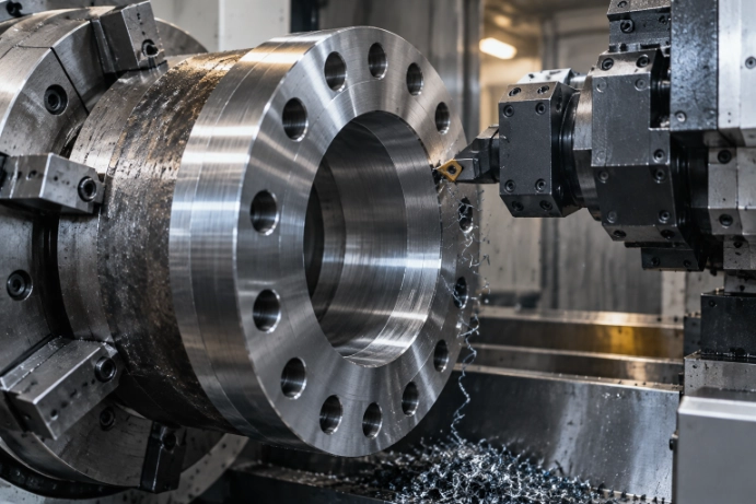
Pipeline Flanges & Connections
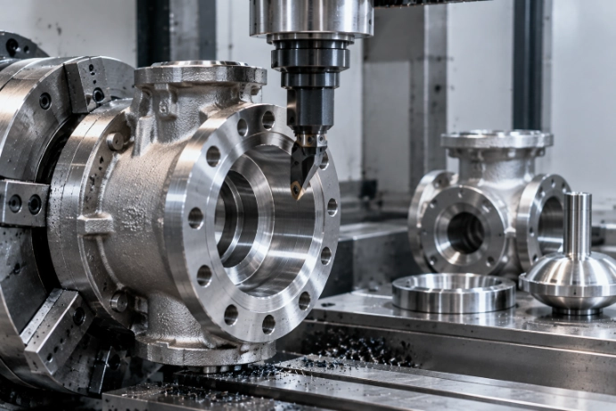
Valves, Bodies & Seats
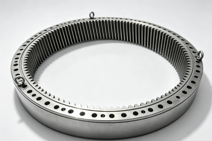
Wind-Turbine Flanges & Shafts
What to Check First in Energy Component Machining
Large energy components create different machining challenges compared with standard parts. Material condition, cutting stability and machine capability should be reviewed before selecting tooling options.
Scale & Interrupted Surfaces
Check First:
· Forging skin
· Weld areas
· Cast surfaces
· Entry conditions
Why It Matters:
Large components often contain uneven surfaces that can influence cutting impact and edge reliability.
Long Cycles & Large Diameters
Check First:
· Tool life by complete operation
· Feature completion
· Wear condition
Why It Matters:
For large parts, tool performance should be evaluated across the full machining process rather than only by cutting time.
Tough Materials & Chip Load
Check First:
· Material condition
· Depth of cut
· Chip control
· Machine power
Why It Matters:
Tough materials require stable cutting conditions to maintain productivity and consistent tool behaviour.
Setup & Repeatability
Check First:
· Clamping
· Tool overhang
· Rigidity
· Results across multiple parts
Why It Matters:
Stable setups are essential for repeatable machining results on large energy components.
Materials and Tooling Considerations
Different mold materials create different requirements for hardness control, tool reach, finishing quality and chip behaviour. Tool selection should begin with understanding the material and machining condition rather than using universal cutting parameters.
| Material | Typical Parts | Common Operations | What to Confirm |
|---|---|---|---|
| Carbon & Alloy Steel | Pipeline flanges, rings, shafts | Turning, facing, drilling, threading | Grade, scale, forging condition, rigidity |
| Stainless & Duplex Steel | Valves, connectors, corrosion-resistant parts | Turning, boring, grooving, drilling | Work hardening, chip control, coolant, toughness |
| Cast Steel & Cast Iron | Valve bodies, housings, large covers | Turning, facing, milling, boring | Casting skin, inclusions, interruptions, edge strength |
| Hard-Faced / Hardened Areas | Valve seats, wear surfaces, repaired features | Finishing, profiling, boring | Hardness range, layer condition, interruptions, stability |
Relevant Tool Families
Use these links to understand the available range. For a specific alternative, start with the current tool and application rather than choosing only by appearance.
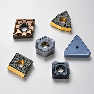
Turning & Facing Inserts
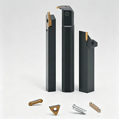
Grooving & Parting Tools
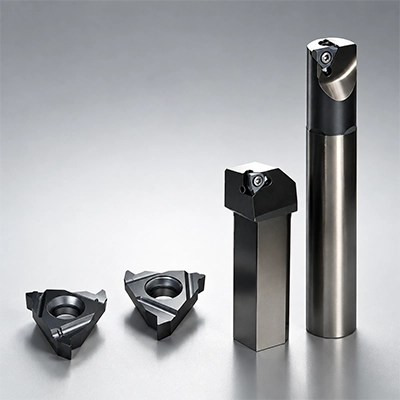
Threading Inserts
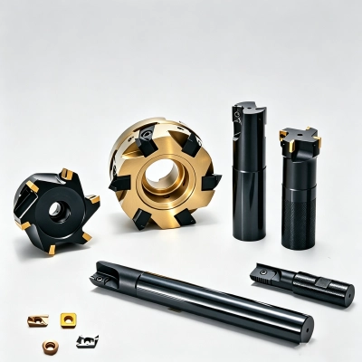
Milling Inserts & Cutters
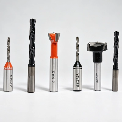
Solid Carbide Drills
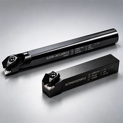
Toolholders & Boring Bars
Your Attractive Heading
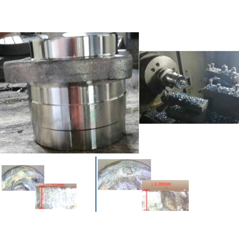
Recorded Insert Comparison in 65Mn Wind-Flange Turning
65Mn · G3-356/01 Wind-Power Flange · Interrupted Rough Internal Turning
Competitor: WNMG080412-TM GradeT***— 110 parts, stopped after edge chipping
Tested: WNMG080412-BTM TP9125 — 120 parts, stopped after edge chipping
Vc 170–190 m/min · fn 0.25–0.40 mm/r · ap 1.5–3.0 mm · Dry Cutting
Because the competitor insert was removed before reaching its final wear limit, this test indicates comparable performance—not a confirmed tool-life increase.
Contact us to request the full test report.
How We Help Evaluate Another Option
A cross-reference is only the starting point. The application decides what is worth testing.

Step 01 Review the Component and Cut
-
Start by reviewing the component, material condition, machining operation, setup, current tool and target requirement. These details define the actual cutting conditions before evaluating alternative options.

Step 02 Narrow the Heavy-Duty Options
-
Based on the application requirements, select tooling combinations related to component scale, interrupted surfaces, tool reach and available machine power.
Step 03 Record the Full-Operation Result
-
Compare performance through edge wear, completed features, surface finish and repeatability across parts. Full-operation results provide a more reliable basis for future tooling decisions.
FAQs
-
What information is needed for a pipeline flange or valve application?

-
Share the component drawing or photo, material grade, condition, machining operation, current tool, depth of cut, machine and current problem. For large parts, include diameter and whether the surface is forged, cast, welded or interrupted.
-
Can you review tools for stainless and duplex valve parts?
-
Yes. The material condition, work hardening behaviour, toughness, chip control and coolant delivery should be reviewed before selecting a trial option.
-
How should tool life be recorded on large components?
-
Record completed features or completed parts together with cutting time and wear condition. Minutes alone may not represent actual performance when diameters and engagement conditions change.
-
Do you supply grooving and threading tools for connections?
-
Yes. Groove width, profile, thread form, pitch, tolerance and holder interface should be confirmed before supply.
-
Can we start with a controlled trial?
-
Yes, subject to availability. Use the same material, setup and machining operation so the result can support a repeat-supply decision.
Have a Current Application to Evaluate?
Send the current tool code and brief application details. We will review the material, operation and what needs to improve before suggesting a practical next step.


